How to Replace factory Q-See QS2350C Power Supply
The Problem
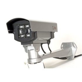
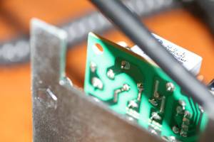
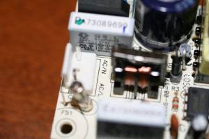
Although the Q-See QS2350C is good quality camera with aluminum case and great night video it has a very lousy power supply. The interference from the power supply is so bad that your neighbors will complain about it.
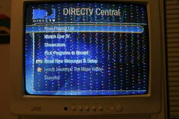
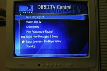
Here are two photographs of before and after. This television has a Tivo connected to it via a COAX and is tuned to CH 3. The QS2350C is not even close to the TV and causes massive interference.
Replacement Power Supply
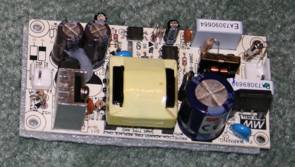
The replacement power supply I decided to use is a RoHS certified universal power supply from Mean Well. You can get them at mouser under part number 709-PS15-12.
709-PS15-12 Details
 Input: 85 ~ 264VAC (47 ~ 63Hz ) or 120 ~ 370VDC
 Output: 12V 1.25A
 Power: 15W
 Compliance to EN55022 (CISPR22) Class B
 Compliance to EN61000-3-2,-3
 Compliance to EN61000-4-2,3,4,5,6,8,11 Light industry level,  criteria A
The new power supply is a bit smaller than the original and the mounting holes do not match up exactly so you must be careful not to short the board to the case.
Tools Required
In order to replace the power supply you will need some experience in soldering but that is about it. Here is a list of itmes you will need:
- Soldering Iron and Solder (Lead free preferred of course)
- Hot Glue gun
- A set of Philips and slotted screw drivers
- Some stand-offs
- Replacement Power supply ( Mouser Part 709-PS15-12)
Removing Original Power Supply
WARNING: This can be dangerous. Please follow safety guidelines.
I take no responsibility for your actions.
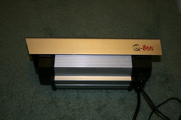
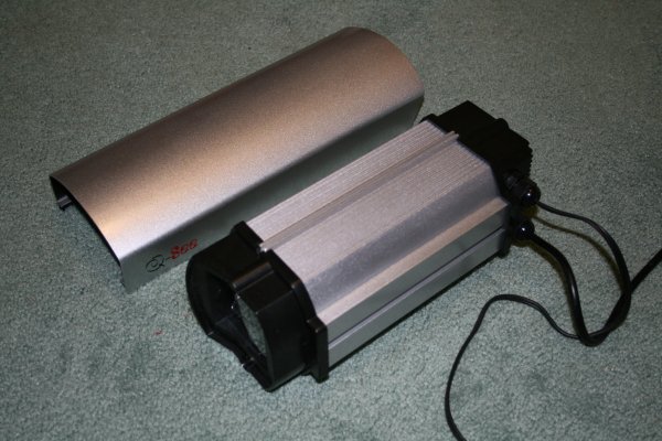
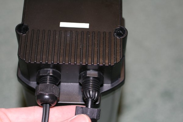
Slide Off the rain shield
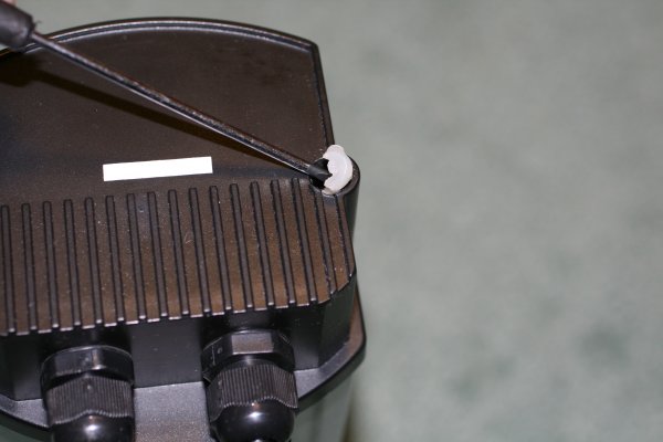
Pry out the Hot Glue that is in the screw holes using a small flat head screw driver.
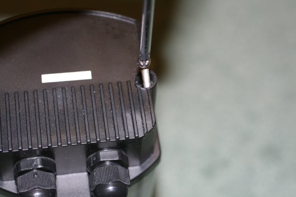
Unscrew the two Philips screws
Remove the wire lock screws
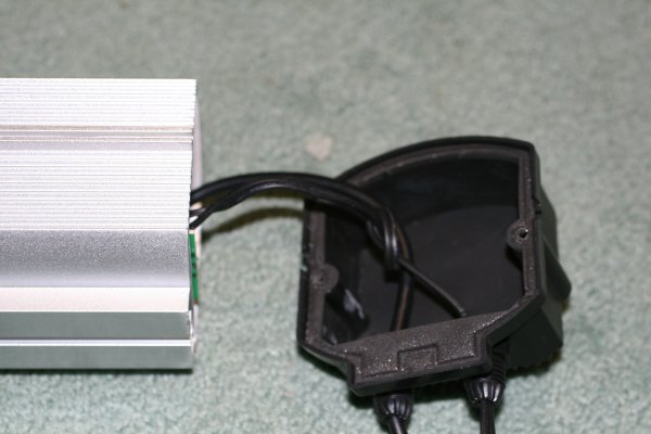
Careful pry open the back of the case
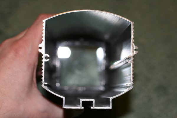
Apply pressure to the top and bottom of the aluminum case and slide out the PCB assembly. By applying slight pressure to the top and bottom you expand the sides making it easier to pull out the aluminum plate with the PCBs on it.
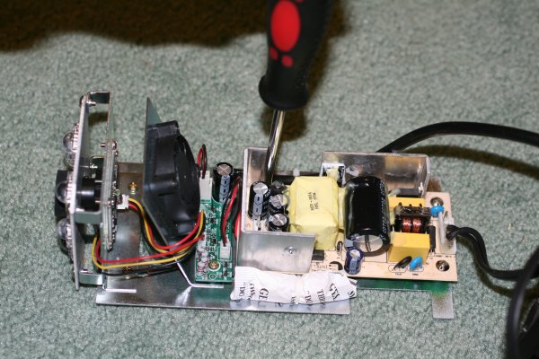
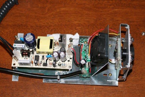
Remove the power supply PCB.
Installing New Power Supply
Electrical
WARNING: This can be dangerous. Please follow safety guidelines.
I take no responsibility for your actions.
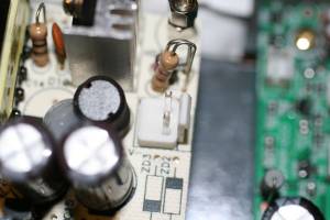
Remove the AC cord from the original power supply and remove the small red/black wire going to the PCB.
Re-attach the AC cord to the new power supply making sure that you solder AC/N and AC/H accordingly.
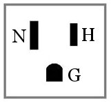
 AC/N = Neutral (larger of the two pins on ac AC cord)
 AC/H = Hot (smaller of the two pins on an AC Cord)
Note: If your AC cord does not have two different sized pins it wont matter how you connect it. The new power supply will work either way.
Re-attach the Red and black wires to the V- and V+
 V+ = Red Wire
 V- = Black Wire
Add hot glue to the contacts so they don't move when you put the board back in the case.
Mounting
Since the new power supply is smaller and the mounting holes don't match exactly the original power supply you need to pay attention not to short out any part of the board.
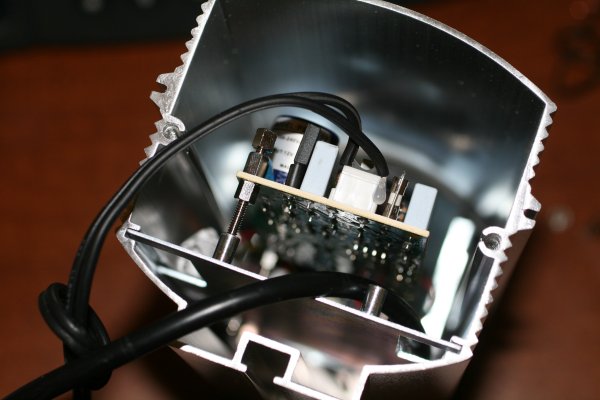
If you look at the image you can see I used three stand-offs two of which the board is mounted down on.
The third stand-off is just to provide support to the board. It also rests on an area of the board that does not have any active connections therefore not shorting anything to the case.
As you can see the reason I did not use the fourth standoff is because it would have rested on the AC line and shorted to the case of the camera. You could use a Nylon stand-off but I don't have any when I installed the new power supply.
Re-assembly
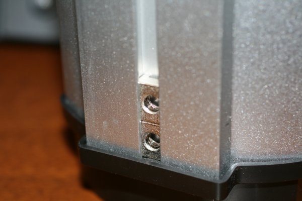
Put everything back together in reverse order you took it apart. Don't forget to put the two mounting nuts back in the rail as shown below. Also add hot glue back into the two screw holes to keep the unit water tight.
